|
| Home >> Product >> View product |
Glass Vessels |
2008-11-18 15:21:55 |
Vessels are used as reactors, receivers, separators, measuring, feeds etc. Vessels can be used under full vacuum and as per given below working pressure (Bar g).
Vessels are available in spherical / cylindrical shape from 5Ltr. to 300Ltr. capacity. Vessels are provided with a bottom outlet nozzle, for which a suitable valve can be chosen from range of valves.
| SPHERICAL VESSELS GENERAL DATA |
| |
 |
NOMINAL
CAP. (LTR.) |
BULB
DIAMETER
MM
D |
MAXIMUM
INTERNAL
PRESSURE
(Bar g) |
TOLERANCE
OF
DIAMETER
MM |
TOLERANCE
IN LENGTH
MM
L |
| 5 L |
220 |
1.0 |
± 2 |
± 5 |
| 10 L |
285 |
0.8 |
± 2 |
± 5 |
| 20 L |
350 |
0.7 |
± 2 |
± 5 |
| 50 L |
470 |
0.5 |
± 3 |
± 5 |
| 100 L |
600 |
0.4 |
± 4 |
± 5 |
| 200 L |
750 |
0.20 |
± 5 |
± 8 |
| 300 L |
850 |
0.25 |
± 6 |
± 8 | | |
 |
| SINGLE NECK SPHERICAL VESSELS |
| |
|
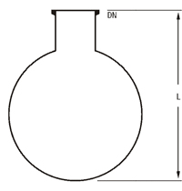 |
| Nominal capacity(Ltr.) |
DN (mm) |
L (mm) |
Cat. Ref. |
| 5 L |
40 |
270 |
SVSA 5 |
| 10 L |
40 |
350 |
SVSA 10 |
| 20 L |
80 |
430 |
SVSA 20 |
| 50 L |
100 |
590 |
SVSA 50 |
| 100 L |
150 |
740 |
SVSA 100 |
| 200 L |
225 |
910 |
SVSA 200 |
| 300 L |
300 |
1025 |
SVSA 300 | |
|
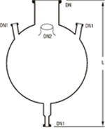
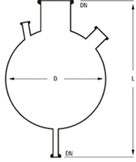
| HREE NECK BOTTOM OUTLET SPHERICAL VESSELS |
| |
|
 |
| Nominal capacity (Ltr) |
DN |
DN1 |
L |
Cat. Ref. |
| 5 L |
40 |
25 |
345 |
SVSM 5 |
| 10 L |
40 |
25 |
425 |
SVSM 10 |
| 20 L |
80 |
25 |
525 |
SVSM 20 |
| 50 L |
100 |
40 |
690 |
SVSM 50 |
| 100 L |
150 |
40 |
840 |
SVSM 100 |
| 200 L |
225 |
40 |
1020 |
SVSM 200 |
| 300 L |
300 |
40 |
1155 |
SVSM 300 | | |
 |
| |
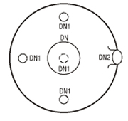
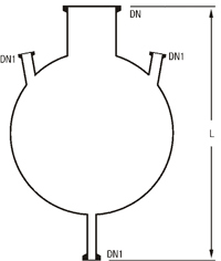
| SPHERICAL VESSELS WITH NOZZLE AT 90° |
| These vessels are used in circulatory boiler system. More nozzles can be provided on the equator on request . |
|
|
| Nominal capacity (Ltr) |
DN |
DN1 |
DN2 |
L |
Catalogue Reference |
| 5 L |
40 |
25 |
25 |
345 |
SVSD 5 |
| 10 L |
40 |
25 |
40 |
425 |
SVSD 10 |
| 20 L |
80 |
25 |
40 |
525 |
SVSD 20 |
| 50 L |
100 |
40 |
80 |
690 |
SVSD 50 |
| 100 L |
150 |
40 |
80 |
840 |
SVSD 100 |
| 200 L |
225 |
40 |
80 |
1020 |
SVSD 200 |
| 300 L |
300 |
40 |
80 |
1155 |
SVSD 300 | | |
|
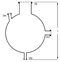
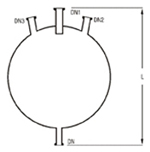
| RECEIVERS SPHERICAL VESSELS |
| Receivers are provided with built-in drip pipe. |
|
|
| Nominal capacity |
DN |
DN1 |
DN2 |
DN3 |
L |
Catalogue Reference |
| 5 L |
25 |
25 |
25 |
- |
345 |
SVR 5 |
| 10 L |
25 |
25 |
25 |
- |
425 |
SVR 10 |
| 20 L |
25 |
25 |
25 |
- |
525 |
SVR 20 |
| 5 L |
25 |
25 |
25 |
25 |
345 |
SVR 5 |
| 10 L |
25 |
25 |
25 |
25 |
425 |
SVR 10 |
| 20 L |
25 |
25 |
25 |
25 |
525 |
SVR 20 | |
| |
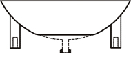
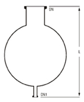
| ADDITION SPHERICAL VESSELS |
| These vessels are provided with a short bottom outlet. It should be supported on a vessel holder/ holding ring. |
|
|
| Nominal capacity |
DN |
DN1 |
L |
Catalogue Reference |
| 5L |
40 |
25 |
345 |
SVA 5 |
| 10 L |
40 |
25 |
425 |
SVA 10 |
| 20 L |
80 |
25 |
525 |
SVA 20 |
| 50 L |
100 |
40 |
690 |
SVA 50 |
| 100 L |
150 |
40 |
840 |
SVA 100 |
| 200 L |
225 |
40 |
1020 |
SVA 200 |
| 300 L |
300 |
40 |
1155 |
SVA 300 | |
|
| | |
|
| |
| BATHS |
| COOLING BATHS |
| Cooling baths are used for cooling the glass vessel with ice crystals. Cooling baths are provided with a vessel holding ring, bottom outlet sealing arrangement and a lid. |
|
|
| VESSEL CAP. (LTR.) |
D |
L |
CAT. REF. |
| 5 |
325 |
350 |
SBHC 5 |
| 10 |
350 |
250 |
SBHC10 |
| 20 |
480 |
330 |
SBHC20 |
| 50 |
615 |
415 |
SBHC 50 |
| 100 |
720 |
510 |
SBHC100 |
| 200 |
900 |
620 |
SBHC200 | |
|
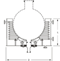
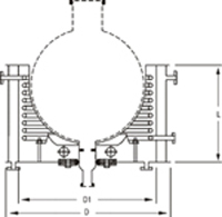
| HEATING BATHS - WITH COIL & HEATER |
| M.S. Heating baths are used with electrical or steam heating for glass vessel. Depending upon the temperature requirements, different types of thermic fluids or water can be used as heating media. Heating baths are provided with a pair of non flame proof heaters, M.S. Coil for passing the steam or cooling water, cushioned vessel holder, a bottom outlet sealing arrangement, a lid and threaded socket type or flange type inlet and outlets. |
|
|
| VESSEL CAP. (LTR.) |
D |
L |
LOADING KW |
CAT. REF. |
| 5 L |
325 |
225 |
2 (2x1000) |
SBH 5 |
| 10 L |
350 |
250 |
2 (2x1000) |
SBH 10 |
| 20 L |
480 |
330 |
3 (3x1000) |
SBH 20 |
| 50 L |
615 |
415 |
4.5 (3x1500) |
SBH 50 |
| 100 L |
720 |
510 |
6 (3x2000) |
SBH 100 | |
| |
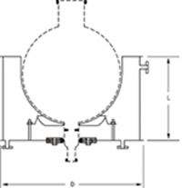
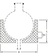
| HEATING BATHS - JACKETED WITH COIL |
MS Jacketed heating bath is provided with a coil inside to circulate either steam or heat transfer fluid depending upon the application. Provision for insertion of Electrical heater is also kept.
(Non-flame proof) Heater can also be provided along with the bath on request. Although the standard heating baths are specifically designed for spherical vessels, similar baths for cylindrical vessels can also be supplied to special order. All these heating baths can be fitted with suitable temperature control equipment if required. |
|
|
| VESSEL CAP. (LTR.) |
D1 |
D |
L |
CAT. REF. |
| 5 L |
325 |
395 |
260 |
SBHD5 |
| 10 L |
350 |
420 |
285 |
SBHD10 |
| 20 L |
480 |
550 |
365 |
SBHD 20 |
| 50 L |
635 |
685 |
465 |
SBHD 50 |
| 100 L |
730 |
830 |
560 |
SBHD 100 |
| 200 L |
900 |
1050 |
680 |
SBHD 200 | |
| |
| Notes: |
Powder coating / S.S. Heating bath can be supplied on request. This should be specified during inquiry stage.
S.S./ Copper coil can be supplied on request. This should be specified during inquiry |
|
| HEATING MANTLES |
As an alternative to heating baths electric heating mantles can also be supplied for spherical vessels. Their heating power varies according to the nominal capacity of the vessel involved.
These heating mantles are subdivided into several heating zones each of which is equipped with a temperature probe so that the surface temperature of the vessel can be monitored. These work in conjunction with the control unit included in the supply to prevent local hot spots occurring. The control unit also includes energy regulators, which can be used to control the heat input separately for each heating zone depending on the liquid level. |
|
|
| CAPACITY VESSELS |
D |
L |
LOADING KW |
CIRCUITS |
SUPPLY |
CAT. REF. |
| 5 |
- |
- |
0.6 (1x600) |
1 |
230V |
SJMD 5 |
| 10 |
- |
- |
1.0 (2X500) |
3 |
230V |
SJMD 10 |
| 20 |
470 |
245 |
1.5 (3X500) |
3 |
230V |
SJMD 20 |
| 50 |
610 |
305 |
3.6 (6X900) |
3 |
440V |
SJMD 50 |
| 100s |
715 |
360 |
5.4 (6X900) |
3 |
440V |
SJMD100 |
| 200 |
890 |
450 |
8.1 (9X900) |
3 |
440V |
SJMD 200 | | |
|
| |
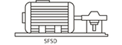
| MOTOR WITH REDUCTION GEAR BOX |
Flameproof motor with reduction gearbox is supplied as standard. A motor is coupled with gearbox. The other end of the gearbox is coupled with flexible shaft.
1:7 Reduction gearbox is used with motor. 1:10 reduction gearbox can also be supplied on request. This should be specified at the time of enquiry stage. |
| SPECIFICATION : 1400 RPM, 415V, 50Hz, 3 Phase supply, insulation class F, degree of protection : IP 55. |
|
|
| H.P. |
SPEED |
CAT. REF. |
| 0.5 |
190 |
SFSD 0.5/190 |
| 0.5 |
130 |
SFSD 0.5/130 |
| 0.25 |
190 |
SFSD 0.25/190 | |
|
| SPEED VARIATOR |
|
|
Different variable speed stirrer drives are available for adjusting stirrer speeds to different operating conditions. |
|
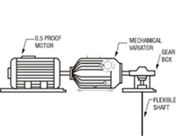
| MECHANICAL VARIATOR |
| Mechanical variator have been designed for either horizontal or vertical mounting, one end of the mechanical variator is coupled with motor shaft and other end is fitted with reduction gear box. Control for speed regulation is attached to one end of the control shaft. Hand wheel control is standard control provided on the unit, where selected speed can be read on the indication drum. Variable output speed between lowest 1/7 of the input speed and highest 1.7 times of the input speed can be adjusted. The variator can run in either direction at the rated HP. |
|
| FREQUENCY VARIATOR |
Non-flameproof digital microprocessor AC variable speed drives (inverters) is also available to adjust the speed of motor. This VARIATOR has got LED display for frequency, speed, setting value, voltage etc. Frequency is set by keypad or external analog signal.
Power supply: 3 Phase, 440V, 50Hz.
Flameproof version can also be supplied on request. This should be specified at the time of enquiry stage. | |
|
| |
| MESUEMENT AND CONTROL |
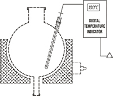
| DIGITAL TEMPERATURE INDICATOR |
|
|
This instrument is mainly used to monitor of liquid in a typical glass distillation unit.
This instrument mainly consists of : temperature Indicator and Resistance Temperature Detectors (RTD). This instrument works on 230V, 50 Hz power supply. This displays the temperature in degree Centigrade (°C). |
| VESSEL CAPACITY (Ltr.) |
RTD LENGTH |
CAT. REF. |
| 20 |
400 |
SDTI 20 |
| 50 |
500 |
SDTI 50 |
| 100 |
600 |
SDTI 100 | |
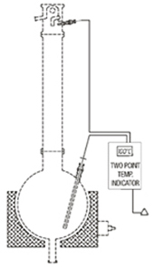
| TWO POINT DIGITAL TEMPERATURE INDICATOR |
|
|
This instrument is mainly used to monitor temperature of liquid in a glass vessel and temperature of vapours of reflux divider in a typical glass distillation unit. This instrument mainly consists of Temperature Indicator and Two Resistance Temperature Detectors (RTD). This instrument works on 230V, 50Hz power supply. This display temperature in degree Centigrade (°C) a switch is provided to see the two temperature alternatively.
| VESSELS CAPACITY(Ltr.) |
RTD LENGTH FOR VESSEL |
RTD LENGTH FOR REFLUX DIVIDER |
CAT. REF. |
| 20 |
400 |
200 |
STDTI 20 |
| 50 |
500 |
225 |
STDT50 |
| 100 |
600 |
250 |
STDTI 100 |
| 200 |
700 |
300 |
STDTI 200 | | |
| |
| |
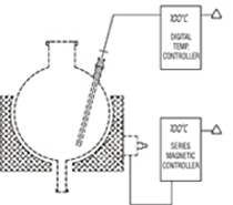
| CONTINUOUS TEMPERATURE CONTROLLER |
| |
|
|
This instrument displays and controls temperature continuously by switching the power supply ON and OFF in an electrical heating equipment as per the initial settings of heating temperature, band width and reset temperature. This instrument mainly consists of a Temperature controller, a series magnetic controller and a Resistance Temperature Detectors(RTD).
RTD is put into the thermometer pocket of the glass vessel and desired settings are done. As temperature, in the vessels reaches to the set heating temperature, the temperature controller cuts the power in heating equipment OFF. Power starts ON again as the temperature goes down as per the settings of band width and reset temperature. |
| This instrument works on power supply of 230V 50Hz and can be used with heating mantles and heating baths of all sizes. It displays temperature in Degree Centigrade |
| VESSEL CAPACITY (Ltr.) |
RTD LENGTH |
CAT. REF. |
| 20 |
400 |
SCTC 20 |
| 50 |
500 |
SCTC50 | |
| |
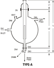
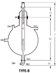
| SEPARATORS |
|
|
Separators are used to separate two immiscible liquids with different densities. When these liquids allowed settling forms two separate layers, heavier at bottom and lighter at up. Mixture of liquid is continuously feeded in separator at low velocity. This allow sufficient residence time for the formation of separating layers. Light phase liquid is continuously removed from light phase outlet at the top. The Heavy phase liquid enters through dip pipe at lower end and overflows in the discharge pipe and is removed from the bottom outlet.
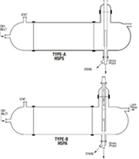
Separator can be provided with Adjustable overflow valve, (Type B) to adjust position of interface for different operating situations. Separator can also be constructed with horizontal cylindrical vessel and to provide lager-separating surface. (Cat Ref. HSPS OR |
|
|
| NOM. CAP. |
DN |
INLET DN1 |
DN2 |
HEAVY PHASE OUTLET DN3 |
DRAIN DN4 |
LIGHT PHASE OUTLET DN5 |
VENT DN6 |
L |
L1 |
L2 |
L3 |
TYPE |
CAT.REF. |
| 20L |
80 |
25 |
50 |
25 |
25 |
25 |
25 |
80 |
125 |
525 |
- |
A |
SSPS20 |
| 50L |
100 |
40 |
50 |
25 |
25 |
40 |
40 |
1025 |
150 |
725 |
- |
A |
SSPS50 |
| 100L |
150 |
40 |
50 |
25 |
25 |
40 |
40 |
1175 |
200 |
825 |
- |
A |
SSPS100 |
| 200L |
225 |
40 |
50 |
25 |
25 |
40 |
40 |
1475 |
250 |
1075 |
- |
A |
SSPS200 |
| 20L |
80 |
25 |
50 |
25 |
25 |
25 |
25 |
1000 |
125 |
525 |
200 |
B |
SSPS20 |
| 500L |
100 |
40 |
50 |
25 |
25 |
40 |
40 |
1225 |
150 |
725 |
200 |
B |
SSPS50 |
| 100L |
150 |
40 |
50 |
25 |
25 |
40 |
40 |
1375 |
200 |
825 |
200 |
B |
SSPS100 | | |
| |
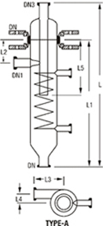
| CYCLONES |
|
|
Cyclones are designed for separation not only for droplets from gases and vapours, but also for particulate solids form gases.
The overall degree of separation can be as high as 99% but this figure is governed to a large extent by the following factors.
|
* |
Liquid loading of the gas or vapour or solids loading of the gas. |
|
* |
Droplet or particle size range. |
|
* |
Droplet or particle size distribution. | |
| The following are examples of limiting droplet diameters for the standard air/water system(at ambient temperature) with a velocity in the dip pipe of 15m/sec | |
| |
|
|
| DN |
DN1 |
DN2 |
DN3 |
DN4 |
L |
L1 |
L2 |
L3 |
L4 |
L5 |
CAT.REF. |
| 100 |
40 |
25 |
80 |
40 |
415 |
560 |
130 |
125 |
35 |
180 |
SCY4 |
| 150 |
50 |
25 |
100 |
50 |
850 |
665 |
165 |
150 |
55 |
235 |
SCY6 |
| 225 |
80 |
25 |
150 |
80 |
1120 |
870 |
225 |
200 |
75 |
320 |
SCY9 | |
| |
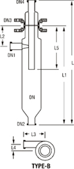
| CYCLONES WITH INTERNAL COOLING COIL |
|
|
| DN |
DN1 |
DN2 |
DN3 |
L |
L1 |
L2 |
L3 |
L4 |
L5 |
CAT.REF. |
| 100 |
40 |
25 |
40 |
715 |
560 |
130 |
125 |
35 |
330 |
SCY 4 |
| 150 |
50 |
25 |
50 |
850 |
665 |
165 |
150 |
55 |
375 |
SCY 6 |
| 225 |
80 |
25 |
80 |
1120 |
870 |
180 |
200 |
75 |
500 |
SCY 9 |
| 300 |
100 |
25 |
100 |
1430 |
1155 |
215 |
275 |
100 |
675 |
SCY 12 | | |
| |
|
| |
|
|